Your cart is currently empty!
What is an Accelerometer
How does a MEMS Accelerometer Work?
Acceleration is the change in velocity. A stationary body has no acceleration, and a body moving at a constant velocity has no acceleration. However, a body changing from a stationary condition to motion experiences acceleration by means of a force. Newton’s second law establishes this relationship as F=ma.
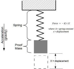
An accelerometer [ak-se-lə-ˈrä-mə-tər] sensor measures the force acting on a known mass to determine “proper” acceleration. There are many ways to measure force, with each method having benefits and limitations. A simple method measures the displacement of a spring-mass system (see ). As a force acts upon the mass, such as gravity, the spring will stretch a certain distance relative to the spring constant. Knowing the spring constant and spring displacement, the force acting upon the mass is calculated. Acceleration is the force divided by the mass.
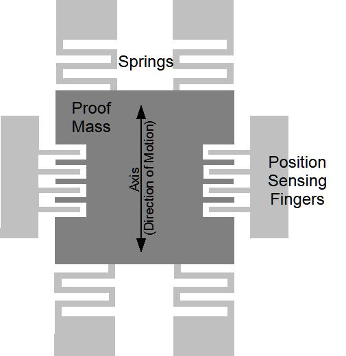
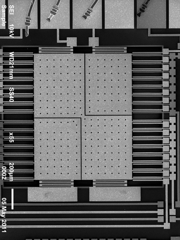
Micro-electro machined sensor (MEMS) technology takes the spring-mass concept and miniaturizes it onto a semiconductor chip. The figure below (left) illustrates the general concept of a MEMS accelerometer system and (right) shows the internal layout of an actual MEMS accelerometer sensor. The mass and spring system is etched into the semiconductor layer. When the sensor experiences an acceleration, the proof mass moves, and the distance between the interleaving “fingers” changes. The change in electrical capacitance between the fingers is proportional to the displacement of the spring-mass system. The capacitance is measured, filtered, and converted to a digital output representing acceleration.
Accelerometer sensors exhibit several types of limitations, including offset error, drift error, sensitivity error, and noise. Offset and sensitivity errors are corrected by calibrating the sensor against known accelerations. Drift errors are typically related to temperature changes but can be minimized by maintaining a consistent environment temperature. Noise is the random variations introduced into the sensor system. Oversampling algorithms and signal filters minimize the effects of sensor noise. Each of these sensor errors affect how the data is processed into a usable result. For example, integrating acceleration to determine displacement is heavily skewed due to the drift and noise characteristics of the sensor.
Accelerometer sensors detect translation motion within the axis of the proof mass. Rotational motion causes centripetal acceleration that is interpreted as translational motion by the accelerometer. For example, spinning about the z-axis will cause acceleration in the x/y axes even though there is no translational motion in the x/y plane. A gyroscope sensor, which measures rotational velocity about an axis, is needed to discern rotational motion from translational motion. An accelerometer sensor and gyroscope sensor are required to determine the six variables of 3D motion. This combination of sensors is considered an inertial measurement unit (IMU) system. Some IMU systems, such our IMU-GPS logger, include an additional magnetometer sensor (compass) and GPS to further aid the calculations of motion.